|
|
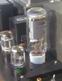
Svetlana SV572-3 Single Ended Power Amplifier |
By SEKIDO Ryoichi (E-Mail: rsekido@cityfujisawa.ne.jp)
Project Completed: July 1997
First Edition: Sep 2 1997
Last Updated: Nov 12 1997
This mono block amplifier features Svetlana's new comer, SV572-3, as in the single ended power stage.
It was half a year ago, I happened to use the Internet, seeking audio WEB sites, then I came across this massive new tube on the Svetlana's home page.
Thanks to Svetlana's WEB master, it was very easy to download their detailed data sheets. Those really fascinated me because of its huge plate dissipation (125W !) and of beautiful plate linearity.
I at once brought a pair of tubes and started a new amplifier design.
About the Svetlana SV572-3
This brand new tube was unveiled in 1996 from Svetlana Electron Devices. They formerly released SV811 series which is a modified version of the same named existing transmitting tube. Unlike SV811, SV572 might not have a corresponding tube.(*)
It also has four variants by amplification factor, each called SV571-3, Sv572-10, SV572-30 and SV572-160 respectively. In this time, SV572-3 has been chosen because of its fitness for audio power tube.
Here is the main characteristics and a typical single ended operation. (Table-1, Table-2, Table-3)
It looks like a small UV-211 but its base is a ceramic UX 4 pins. Surprisingly, SV572 has a 125w of plate dissipation which exceeds UV-211's 75W and 100W. Shown in Table-3, in class A2 operation, it carries a 25W of power at 750V Eb and 140mA Ib. This means that operation is easier than 211 or 845.
The filament consumes 6.3V and 4A, that is less than 211 or 845, and illuminates like a bulb one could read a newspaper in the dark.
The structure looks rigid and highly reliable. It has no getters on the glass envelope but the massive titanium coated graphite plate may degas the tube.
The other data is shown in Table-4.
(*) I was noticed from a reader stating that there exists a transmitting tube named 572B which has been used for 500W class transmitter. From his notice, its construction looks like two 811 in a tube. Considering the spec, however, SV572 is not seemed to be the same series of 572B.
An Overview
The amplifier consists of a plate supply, a DC filament supply, a bias supply, a two stage voltage amplification and a power stage.
Since the power stage consumes high voltage and many DC current, each DC supplies are provided all through silicone rectifiers.
Respective stages use the following tubes; a 6SL7GT parallel as the first stage, a 6BX7GT parallel as the driving stage and a SV572-3 as the power stage.
In this amplifier, the output stage needs more than 700V as the plate voltage, 100mA as the plate current and also needs -150V as the grid bias. Since this bias is very exceptional, the driving stage have to do a tough work.
The First Stage and the Driving Stage
The first stage and the driving stage consists of two tubes; 6SL7GT and 6BX7GT. Respective tubes are utilized as a conventional plate follower and also wired as a parallel operation. Considering my previous made tiny 3 watts amplifier, featuring 6SL7GT - 6BX7GT, which sounds natural and gentle, it was expected this lineup might be a good driver for SV572-3.
The parallel operation is intended for reducing plate resistance and consequently improving frequency response in high frequency.
An important issue of the driving stage is that it needs more than 100V rms to drive a SV572-3. Also, the restriction of grid resistance of SV572-3 is unknown from the data sheets. Generally speaking, directly heated tubes tend to flow considerable grid current. So, it might be better than the grid resistance is not high. In such case, the interstage transformer is an answer since old times. However, there is another ancient method which inserts a choke coil in driver's plate load. For example, this method was introduced in Asano's well known book [1] as '50 single ended power amplifier. Also, Reich's famous textbook [2] states the advantages of the inductance-capacitance coupling comparison to transformer coupling or resistance-capacitance coupling. In this amplifier, the plate-choke drive has been applied to drive a SV572-3. The applied inductance is TANGO TC-30-50 which has a 30H inductance and handles a 50mA of maximum DC current.
The schematic is shown in Figure-1. The first stage is just an ordinary voltage amplifier. In the second stage, however, one of the the 6BX7's load, which is also the grid resistance of SV572-3, must be considered. As noted above, it is preferable that the grid resistance is as low as possible and is expected powerful sounds which can be derived from such a low impedance drive.
From the prior experiments, the grid resistance fixed at 10Kohms. Since the driving voltage 100V with the 10Kohms, these stages are equivalent to a tiny power amplifier providing 1 watts with low distortion.
Finally, a minor loop NFB can be applied from 6BX7's plate to 6SL7's cathode. The amount may be 4dB to 6dB, it aimed to make a frequency range wide rather than reduce the distortion. There may also be an overall NFB from the secondary of output transformer. It will be useful to switch a minor NFB and an overall NFB.
The Output Stage
Now prepared the driving stage, the next issue is the construction of the power stage. From the Eb - Ib data, the following operations may be appropriate. (Also shown in Figure-2)
| Eb | 735V |
|---|---|
| Ib | 100mA |
| Ec | -135V |
| RL | 5 Kohm |
| Expected Power | 15W |
For more power, higher Eb and Ib with class A2 operation may be acceptable. In this time, however, those operations have been differed because it is preferable to explore the straightforward characteristics of SV572-3.
The bias is extra deep -135V and the power supply's capacity is limited, it can't handle with a self bias operation, so an independent fixed bias supply is required. Also, to reduce the hum, a DC filament supply must be needed.
The applied output transformer is TANGO XE60-5-SNF which has a 5Kohm as a primary impedance and can handle a 40W power at 30Hz. Since it has a special winding for NFB, a shallow overall NFB (major loop) can be applied from the secondary to the first stage. As mentioned above, it can be switched either a minor loop or major loop NFB. The major loop NFB has set to 4dB.
Finally, there added a voltage meter to monitor a plate current during the operation.
The schematic is shown in Figure-1. Note that the grid resistor of SV572-3 consumes no little power. So, it needs sufficient wattage to avoid burning up. In this case, the resistor is used in parallel with 20K/3W and 18K/3W, a total of 9.7K/6W. This is a consequence of the prior experiments, a single 10K/3W is also acceptable.
The Power Supply
The power supply section is relatively a large scale. It consists of B+ for power tube, B+ for prior stage, C- for power tube bias, DC filament supply for power tube and heater supply for prior stage. All DC supplies are provided by silicone rectifiers because of getting the B+ voltage as higher as possible and of the restriction of chassis dimensions.
The schematic is shown in Figure-3.
When starting up, 180mA of rush current is observed in power tube. This is caused by a delay of bias supply. Though the rush current dose not exceed the limitation of SV572-3, a delay circuit may be needed in plate supply.
The power transformer TANGO MS-155 has a 550V and a 250V with a center tap and two 7.5V/4.5A. The power stage B+ is provided with 550V full wave rectification. The other B+ and C- are provided also with 250V full wave. The rectifiers used have the capacity of 1500V/1A. Also, two of them are used in serial for the 550V line.
The DC filament supply, which needs 6.3V/4A, are obtained by two 7.5V/4A in parallel. It also needs two 15,000MF capacitors to reduce filament hums. The rectifier is bridge type with 250V/20A. It is desired more larger size because it becomes relatively hot.
The Parts
The Measurements
The measurements have been made as follows.
| Oscillator | KENWOOD AG-203A |
|---|---|
| AC volt meter | KENWOOD VT-171 |
| Distortion analyzer | Hewlett-Packard 331A |
| Oscilloscope | IWATSU SS-5215 |
With no NFB, the clip are seen at 0.56V of input with 18.6 watts. With 4dB NFB, the clip moves to 0.9V and 18.0 watts. (Figure-4 and Figure-5)
The frequency bandwidth stays in 30Hz - 25KHz at -1dB point without NFB. This becomes slightly wide with minor loop NFB. With major loop NFB, a tiny peak is observed around 12Hz. This may be caused by an inductance in the feed back loop. However, the peak frequency is out of audible limit, it may hardly make any problems. These results are shown in Figure-6.
As shown in Figure-7, The THD without NFB is 0.7% at 1W and 5% is near 20W. This means the amplifier is fully usable with no NFB.
With minor loop NFB, the THD becomes slightly lower except low frequency. (Figure-8)
The Figure-9 shows the THD with major loop NFB. It goes down more fewer than minor. As mentioned below, it seems that lower THD does not always sound good. In this amplifier, it sounds slightly solid with major loop NFB.
At each tested frequencies, from low to high level, the oscilloscope detected only a second THD. That shows a typical phenomenon of well-linearized triodes.
The other characteristics are shown below.
| Residual noise(without NFB) | 0.9mV |
|---|---|
| Residual noise(with minor and major NFB) | 0.65mV |
| Damping factor | about 2.0 at 1KHz/1W |
The Listening Test
The components used through the listning tests are shown in table-8.
| Turn table | GARRARD 401 |
|---|---|
| Tone arm | AUDIO TECHNICA AT-1501 II |
| Cartridge | SHURE Me97-HE |
| CD player | DENON DCD-1650GL |
| Pre-Amplifier | Tube type CR equalizer with SRPP |
| Reference Amplifier | VT-62/801A SE |
| Speakers | JBL L220 |
A reference power amp selected here also resembles the tested amp, both are directly heated and need high plate voltage.
The test sources are listed bellow.
Through the testing, the NFB has almost set to minor loop. That sounds better in many test sources. Of course, no-NFB is quite usable but the major loop NFB tends to be solid and even weak sound.
It couldn't make a distinction between both amps on the first source. Both make a-cappela sound very naturally and I always think human voices could be a good example for test.
The second source, however, sounds better with the SV572-3, especially on guitar and drums. The attack of the strings, snare drum and toms sound clearly.
On the third source, that tendency appears obviously. It expresses the moments stick hitting a drum and a cymbal. It also brings the atmosphere of live recording well.
Karen's voice is bewitching more than the reference amp on the fourth source. Moreover, the electric instruments (eg. guitar, bass, keyboard, etc.) sound slightly powerful and clear.
Though both amp play even on small ensemble like chamber orchestra, the big power of SV572-3 contributes to play symphonies on the fifth source. It dosen't break down even if a strong fortissimo comes.
Generally speaking, tubes with thoriated-tungsten filament is good at playing high frequency and indeed sounds brilliant high-pitched tone. This is applicable to SV572-3. Moreover, it can be said that SV572-3 has both a sensitivity of thoriated-tungsten filament and a big power as massive transmitting tubes. Those characteristics can be obtained by relatively small scale design than existing large transmitting tubes. There is a possibility of more easier operation of SV572-3, so it could be a great tube recently developed.
Acknowledgement
In the prior experiment, I assembled a temporary amp. When I was listening that, one of SV572-3 has blown up suddenly. The dealer, San'ei Denki located at Akihabara Tokyo, kindly agreed to exchange for a new pair. They perhaps made a special order because there was no constant arrivals in that time. I appreciate their kindness.
References
[1] Asano Isamu, "Miwaku no Shinkukan Amp Vol.2", Seibundo-Shinkosya, 1975.
[2] Herbert J. Reich, "Principles of Electron Tubes", Audio Amateur Press, 1995.
 Back to Audio Home.